Product Description
Product Description
Warranty
1 Year
Applicable Industries
Hotels, Garment Shops, Building Material Shops, Manufacturing Plant, Machinery Repair Shops, Food & Beverage Factory, Farms, Restaurant, Home Use, Retail, Food Shop, Printing Shops, Construction works , Energy & Mining, Food & Beverage Shops, Other, Advertising Company
Weight (KG)
1
Showroom Location
Viet Nam
Video outgoing-inspection
Provided
Machinery Test Report
Provided
Marketing Type
Ordinary Product
Warranty of core components
1 Year
Core Components
PLC, Engine, Bearing, Gearbox, Motor, Pressure vessel, Gear, Pump
Material
steel
Place of CZPT
ZheJiang , China
Condition
New
Structure
Shaft
Coatings
Customized
Torque Capacity
Customized
Model Number
Customized
Brand Name
NON
Description
Shaft
Machining equipment
CNC mill,lathe and grind machine
Material
stainless steel, aluminium, carbon
Surface
Grinding and polishing
Shape
Customized
Sampling time
10days
Production time
20days
Packing
Protective packing
Tolerance
±0.001
OEM
Welcome
Production Process
Company Profile
HangZhou HUANENGDA SPRING CO.,LTD
HangZhou HuaNengDa Spring Co., Ltd. is located in Tong ‘an District, HangZhou City, ZheJiang Province, China. It is a hardware factory specializing in R&D design, manufacture and sales of precision components. The company introduces domestic and foreign advanced equipment and production technology, adopts CNC high-precision computer machine, compression spring machine, CNC five-axis linkage machining center, CNC turning and milling compound, 300 tons of punch and other mechanical equipment,and employs senior engineers with more than 10 years of work experience to debug mechanical equipment and customize production.
With the business philosophy of honesty, pragmatism and excellence, HuaNengDa Spring Company is dedicated to serving customers at home and abroad. We hope that the products of HuaNengDa will help your business to be more brilliant, let us build a bright future in the high-tech era!
The testimony is pragmatic and the attitude of the people. Quality service is the pursuit of the people!
Factory Workshop
Production Procedur
Quality Inspection
Packing And Shipping
Our Service
FAQ
1.Small order quantity is workable
From the initial sample design of the spring to the mass production of the springs, we can quickly reach your manufacturing goals and immediately provide the best products because we have an excellent production management system and expertly trained technical personnel.
2.Committed to high quality production
To keep HuaNengDa Springs at the forefront of the industry, we have implemented a stringent internal quality control system and regularly import the latest manufacturing equipment and instruments. Through our precise manufacturing technology and expert mold making process, we provide our customers with the best products and service.
3.Efficiency in manufacturing
Our company’s machinery and equipment are controlled by CNC computers. In order to respond to international needs and standards, we continuously update and upgrade our equipment every year. Our machines effectively increase production capacity and save on manufacturing costs. The manufacturing department is the most important core of the whole company and by treating it with utmost importance, we reap great benefits in manufacturing efficiency.
4.Excellent customization services
HuaNengDa’s R&D team designs and completes customized products according to the needs of customers. From the selection of materials to the function of the products, we can design and develop products to suite different customers’ requirements. We are constantly involving ourselves in all aspects of the industry because only by having a complete view and analysis of the industry, can there be innovative breakthroughs.
Payment term
*T/T : 30% pre T/T, 70% before delivery.
*Trade Assurance
Service
*Delivery on time.
*Shipped by a convenient and cost-effective way.
*Good after-selling, 24 hours service for you.
Packing
*A: Poly bag, Plstic tray ,small box, carton.
*B: According to customers’ requirements.
Delivery
*Sample: 7-10 days after deposit received.
*Batch goods: 12-15 days after samples approved. /* January 22, 2571 19:08:37 */!function(){function s(e,r){var a,o={};try{e&&e.split(“,”).forEach(function(e,t){e&&(a=e.match(/(.*?):(.*)$/))&&1
| Condition: | New |
|---|---|
| Certification: | ISO9001 |
| Standard: | DIN, ASTM, GOST, GB, JIS, ANSI, BS |
| Customized: | Customized |
| Material: | Steel,Stainless Steel,Iron |
| Application: | Metal Processing Machinery Parts |
| Samples: |
US$ 10/Piece
1 Piece(Min.Order) | |
|---|
| Customization: |
Available
| Customized Request |
|---|

Can drive shafts be adapted for use in both automotive and industrial settings?
Yes, drive shafts can be adapted for use in both automotive and industrial settings. While there may be some differences in design and specifications based on the specific application requirements, the fundamental principles and functions of drive shafts remain applicable in both contexts. Here’s a detailed explanation:
1. Power Transmission:
Drive shafts serve the primary purpose of transmitting rotational power from a power source, such as an engine or motor, to driven components, which can be wheels, machinery, or other mechanical systems. This fundamental function applies to both automotive and industrial settings. Whether it’s delivering power to the wheels of a vehicle or transferring torque to industrial machinery, the basic principle of power transmission remains the same for drive shafts in both contexts.
2. Design Considerations:
While there may be variations in design based on specific applications, the core design considerations for drive shafts are similar in both automotive and industrial settings. Factors such as torque requirements, operating speeds, length, and material selection are taken into account in both cases. Automotive drive shafts are typically designed to accommodate the dynamic nature of vehicle operation, including variations in speed, angles, and suspension movement. Industrial drive shafts, on the other hand, may be designed for specific machinery and equipment, taking into consideration factors such as load capacity, operating conditions, and alignment requirements. However, the underlying principles of ensuring proper dimensions, strength, and balance are essential in both automotive and industrial drive shaft designs.
3. Material Selection:
The material selection for drive shafts is influenced by the specific requirements of the application, whether in automotive or industrial settings. In automotive applications, drive shafts are commonly made from materials such as steel or aluminum alloys, chosen for their strength, durability, and ability to withstand varying operating conditions. In industrial settings, drive shafts may be made from a broader range of materials, including steel, stainless steel, or even specialized alloys, depending on factors such as load capacity, corrosion resistance, or temperature tolerance. The material selection is tailored to meet the specific needs of the application while ensuring efficient power transfer and durability.
4. Joint Configurations:
Both automotive and industrial drive shafts may incorporate various joint configurations to accommodate the specific requirements of the application. Universal joints (U-joints) are commonly used in both contexts to allow for angular movement and compensate for misalignment between the drive shaft and driven components. Constant velocity (CV) joints are also utilized, particularly in automotive drive shafts, to maintain a constant velocity of rotation and accommodate varying operating angles. These joint configurations are adapted and optimized based on the specific needs of automotive or industrial applications.
5. Maintenance and Service:
While maintenance practices may vary between automotive and industrial settings, the importance of regular inspection, lubrication, and balancing remains crucial in both cases. Both automotive and industrial drive shafts benefit from periodic maintenance to ensure optimal performance, identify potential issues, and prolong the lifespan of the drive shafts. Lubrication of joints, inspection for wear or damage, and balancing procedures are common maintenance tasks for drive shafts in both automotive and industrial applications.
6. Customization and Adaptation:
Drive shafts can be customized and adapted to meet the specific requirements of various automotive and industrial applications. Manufacturers often offer drive shafts with different lengths, diameters, and joint configurations to accommodate a wide range of vehicles or machinery. This flexibility allows for the adaptation of drive shafts to suit the specific torque, speed, and dimensional requirements of different applications, whether in automotive or industrial settings.
In summary, drive shafts can be adapted for use in both automotive and industrial settings by considering the specific requirements of each application. While there may be variations in design, materials, joint configurations, and maintenance practices, the fundamental principles of power transmission, design considerations, and customization options remain applicable in both contexts. Drive shafts play a crucial role in both automotive and industrial applications, enabling efficient power transfer and reliable operation in a wide range of mechanical systems.

How do drive shafts handle variations in load and vibration during operation?
Drive shafts are designed to handle variations in load and vibration during operation by employing various mechanisms and features. These mechanisms help ensure smooth power transmission, minimize vibrations, and maintain the structural integrity of the drive shaft. Here’s a detailed explanation of how drive shafts handle load and vibration variations:
1. Material Selection and Design:
Drive shafts are typically made from materials with high strength and stiffness, such as steel alloys or composite materials. The material selection and design take into account the anticipated loads and operating conditions of the application. By using appropriate materials and optimizing the design, drive shafts can withstand the expected variations in load without experiencing excessive deflection or deformation.
2. Torque Capacity:
Drive shafts are designed with a specific torque capacity that corresponds to the expected loads. The torque capacity takes into account factors such as the power output of the driving source and the torque requirements of the driven components. By selecting a drive shaft with sufficient torque capacity, variations in load can be accommodated without exceeding the drive shaft’s limits and risking failure or damage.
3. Dynamic Balancing:
During the manufacturing process, drive shafts can undergo dynamic balancing. Imbalances in the drive shaft can result in vibrations during operation. Through the balancing process, weights are strategically added or removed to ensure that the drive shaft spins evenly and minimizes vibrations. Dynamic balancing helps to mitigate the effects of load variations and reduces the potential for excessive vibrations in the drive shaft.
4. Dampers and Vibration Control:
Drive shafts can incorporate dampers or vibration control mechanisms to further minimize vibrations. These devices are typically designed to absorb or dissipate vibrations that may arise from load variations or other factors. Dampers can be in the form of torsional dampers, rubber isolators, or other vibration-absorbing elements strategically placed along the drive shaft. By managing and attenuating vibrations, drive shafts ensure smooth operation and enhance overall system performance.
5. CV Joints:
Constant Velocity (CV) joints are often used in drive shafts to accommodate variations in operating angles and to maintain a constant speed. CV joints allow the drive shaft to transmit power even when the driving and driven components are at different angles. By accommodating variations in operating angles, CV joints help minimize the impact of load variations and reduce potential vibrations that may arise from changes in the driveline geometry.
6. Lubrication and Maintenance:
Proper lubrication and regular maintenance are essential for drive shafts to handle load and vibration variations effectively. Lubrication helps reduce friction between moving parts, minimizing wear and heat generation. Regular maintenance, including inspection and lubrication of joints, ensures that the drive shaft remains in optimal condition, reducing the risk of failure or performance degradation due to load variations.
7. Structural Rigidity:
Drive shafts are designed to have sufficient structural rigidity to resist bending and torsional forces. This rigidity helps maintain the integrity of the drive shaft when subjected to load variations. By minimizing deflection and maintaining structural integrity, the drive shaft can effectively transmit power and handle variations in load without compromising performance or introducing excessive vibrations.
8. Control Systems and Feedback:
In some applications, drive shafts may be equipped with control systems that actively monitor and adjust parameters such as torque, speed, and vibration. These control systems use sensors and feedback mechanisms to detect variations in load or vibrations and make real-time adjustments to optimize performance. By actively managing load variations and vibrations, drive shafts can adapt to changing operating conditions and maintain smooth operation.
In summary, drive shafts handle variations in load and vibration during operation through careful material selection and design, torque capacity considerations, dynamic balancing, integration of dampers and vibration control mechanisms, utilization of CV joints, proper lubrication and maintenance, structural rigidity, and, in some cases, control systems and feedback mechanisms. By incorporating these features and mechanisms, drive shafts ensure reliable and efficient power transmission while minimizing the impact of load variations and vibrations on overall system performance.

Can you explain the different types of drive shafts and their specific applications?
Drive shafts come in various types, each designed to suit specific applications and requirements. The choice of drive shaft depends on factors such as the type of vehicle or equipment, power transmission needs, space limitations, and operating conditions. Here’s an explanation of the different types of drive shafts and their specific applications:
1. Solid Shaft:
A solid shaft, also known as a one-piece or solid-steel drive shaft, is a single, uninterrupted shaft that runs from the engine or power source to the driven components. It is a simple and robust design used in many applications. Solid shafts are commonly found in rear-wheel-drive vehicles, where they transmit power from the transmission to the rear axle. They are also used in industrial machinery, such as pumps, generators, and conveyors, where a straight and rigid power transmission is required.
2. Tubular Shaft:
Tubular shafts, also called hollow shafts, are drive shafts with a cylindrical tube-like structure. They are constructed with a hollow core and are typically lighter than solid shafts. Tubular shafts offer benefits such as reduced weight, improved torsional stiffness, and better damping of vibrations. They find applications in various vehicles, including cars, trucks, and motorcycles, as well as in industrial equipment and machinery. Tubular drive shafts are commonly used in front-wheel-drive vehicles, where they connect the transmission to the front wheels.
3. Constant Velocity (CV) Shaft:
Constant Velocity (CV) shafts are specifically designed to handle angular movement and maintain a constant velocity between the engine/transmission and the driven components. They incorporate CV joints at both ends, which allow flexibility and compensation for changes in angle. CV shafts are commonly used in front-wheel-drive and all-wheel-drive vehicles, as well as in off-road vehicles and certain heavy machinery. The CV joints enable smooth power transmission even when the wheels are turned or the suspension moves, reducing vibrations and improving overall performance.
4. Slip Joint Shaft:
Slip joint shafts, also known as telescopic shafts, consist of two or more tubular sections that can slide in and out of each other. This design allows for length adjustment, accommodating changes in distance between the engine/transmission and the driven components. Slip joint shafts are commonly used in vehicles with long wheelbases or adjustable suspension systems, such as some trucks, buses, and recreational vehicles. By providing flexibility in length, slip joint shafts ensure a constant power transfer, even when the vehicle chassis experiences movement or changes in suspension geometry.
5. Double Cardan Shaft:
A double Cardan shaft, also referred to as a double universal joint shaft, is a type of drive shaft that incorporates two universal joints. This configuration helps to reduce vibrations and minimize the operating angles of the joints, resulting in smoother power transmission. Double Cardan shafts are commonly used in heavy-duty applications, such as trucks, off-road vehicles, and agricultural machinery. They are particularly suitable for applications with high torque requirements and large operating angles, providing enhanced durability and performance.
6. Composite Shaft:
Composite shafts are made from composite materials such as carbon fiber or fiberglass, offering advantages such as reduced weight, improved strength, and resistance to corrosion. Composite drive shafts are increasingly being used in high-performance vehicles, sports cars, and racing applications, where weight reduction and enhanced power-to-weight ratio are critical. The composite construction allows for precise tuning of stiffness and damping characteristics, resulting in improved vehicle dynamics and drivetrain efficiency.
7. PTO Shaft:
Power Take-Off (PTO) shafts are specialized drive shafts used in agricultural machinery and certain industrial equipment. They are designed to transfer power from the engine or power source to various attachments, such as mowers, balers, or pumps. PTO shafts typically have a splined connection at one end to connect to the power source and a universal joint at the other end to accommodate angular movement. They are characterized by their ability to transmit high torque levels and their compatibility with a range of driven implements.
8. Marine Shaft:
Marine shafts, also known as propeller shafts or tail shafts, are specifically designed for marine vessels. They transmit power from the engine to the propeller, enabling propulsion. Marine shafts are usually long and operate in a harsh environment, exposed to water, corrosion, and high torque loads. They are typically made of stainless steel or other corrosion-resistant materials and are designed to withstand the challenging conditions encountered in marine applications.
It’simportant to note that the specific applications of drive shafts may vary depending on the vehicle or equipment manufacturer, as well as the specific design and engineering requirements. The examples provided above highlight common applications for each type of drive shaft, but there may be additional variations and specialized designs based on specific industry needs and technological advancements.


editor by CX 2024-04-04
China High Speed Small Size Single Shaft Ton Bags Shredding drive shaft shop
Item Description
Higher Pace Small Dimension Solitary Shaft Ton Baggage Shredding
Solution Description
MS series one-shaft shredder is a product specifically produced for recycling firms with big squander plastic disposal potential This sequence of solitary-shaft shredders are outfitted with powerful adjustable hydraulic pushers.This layout prevents content jams and lowers put on on the inside rails. The shredder is outfitted with diameter 450mm CZPT powerful V type rotor with width ranging from 1000mm to 2000m . The hydraulic workstation is tightly built-in with the shredder chamber, which saves room and protects the hydraulic station, and is easy to replace and preserve. The style of the normal V-variety rotor, the outfitted cutters, holders as properly as the exterior bearings and hydraulic display screen brackets have been regarded by customers and received great feedback. The MS series shredder can further modify the style according to customers’ needs for squander disposal.
Consumers can choose cooling systems, rotor surface hardening remedy and other anti-put on products.
Software:
The design and style of the MS collection shredder can meet the specifications of numerous squander plastic recycling organizations, such as standard squander recycling, digital squander recycling, and domestic squander recycling processing. There are many kinds of recyclable components, this sort of as numerous plastic blocks, plastic trays, pipes, films, woven bags, and so on., as properly as a variety of varieties of electronic cable waste, ICB buckets, massive family equipment housings, squander paper, waste wood and various organic and natural materials. The size of the mesh monitor can be decided according to the crushing content and the up coming processing demands.
Item Parameters
| Item | Unit | MS4685 | MS46120 | MS46150 | MS46200 |
| Feed opening | mm | 840×1570 | 1120×1570 | 1400×1570 | 1960×1570 |
| Rotor diameter | mm | 457 | 457 | 457 | 457 |
| Rotor pace | rpm | 74 | seventy four | seventy four | 74 |
| Motor electrical power | kw | 37/45/fifty five | 55 | seventy five | 2X55/2×75 |
| Quantity of rotor knives | pcs | sixty | 81 | 102 | one hundred forty four |
| Number of stator knives | pcs | 2×3 | 2×4 | 2×5 | 2×7 |
| Motor of hydraulic unit | kw | 3.seventy five | five.six | five.6 | five.6 |
| Monitor dimension | mm | 40~one hundred | 40~100 | 40~100 | forty~100 |
| Chamber dimension | mm | 800×730 | 800×1000 | 800×1290 | 800×1860 |
Item Information
Company Profile
FAQ
YOU ARE WELCOME TO OUR Manufacturing unit AT ANY TIME
* CZPT is authentic manufacturer.
* If you interested in our items and we can fulfill your request , you could pay out a go to to CZPT Factory.
* The which means of browsing provider, since looking at is believing, CZPT Machinery with very own manufacture and designed& investigation crew, we can send you engineers and make sure the substantial effectiveness following-revenue service.
SEE CZPT Machine HOW TO Make sure THE High quality
* In purchase to guarantee the precision of each and every part, we are outfitted with a selection of professional processing products and we have accrued specialist processing approaches more than the past years.
* Each and every ingredient ahead of assembly demands stringent manage by inspecting staff.
* Every assembly is in charge by a master who has functioning experience for much more than fifteen years
* After all the tools are finished, we will connect all the machines and run the total manufacturing line for at the very least 12 several hours to make certain the secure managing in customers’ manufacturing unit
THE Following-SALE Support OF CZPT Machinery
* Soon after finishing the manufacturing, we will debug the production line, consider pictures, video clips and send them to buyers through mail or quick resources.
* After the commissioning, we will package the gear by the standard export package deal for shipment.
* In accordance to the customer’s request, we can arrange our engineers to customers’ factories to do the installation and education.
* Engineers, income professionals, and following-revenue services administrators will sort an right after-sales group, on the web and offline, to comply with the customers’ project.
|
Shipping Cost:
Estimated freight per unit. |
To be negotiated |
|---|
| After-sales Service: | Local Service Available |
|---|---|
| Warranty: | 2 Years |
| Type: | Powerful Plastic shredders |
| Customization: |
Available
| Customized Request |
|---|
Driveshaft structure and vibrations associated with it
The structure of the drive shaft is critical to its efficiency and reliability. Drive shafts typically contain claw couplings, rag joints and universal joints. Other drive shafts have prismatic or splined joints. Learn about the different types of drive shafts and how they work. If you want to know the vibrations associated with them, read on. But first, let’s define what a driveshaft is.
transmission shaft
As the demand on our vehicles continues to increase, so does the demand on our drive systems. Higher CO2 emission standards and stricter emission standards increase the stress on the drive system while improving comfort and shortening the turning radius. These and other negative effects can place significant stress and wear on components, which can lead to driveshaft failure and increase vehicle safety risks. Therefore, the drive shaft must be inspected and replaced regularly.
Depending on your model, you may only need to replace one driveshaft. However, the cost to replace both driveshafts ranges from $650 to $1850. Additionally, you may incur labor costs ranging from $140 to $250. The labor price will depend on your car model and its drivetrain type. In general, however, the cost of replacing a driveshaft ranges from $470 to $1850.
Regionally, the automotive driveshaft market can be divided into four major markets: North America, Europe, Asia Pacific, and Rest of the World. North America is expected to dominate the market, while Europe and Asia Pacific are expected to grow the fastest. Furthermore, the market is expected to grow at the highest rate in the future, driven by economic growth in the Asia Pacific region. Furthermore, most of the vehicles sold globally are produced in these regions.
The most important feature of the driveshaft is to transfer the power of the engine to useful work. Drive shafts are also known as propeller shafts and cardan shafts. In a vehicle, a propshaft transfers torque from the engine, transmission, and differential to the front or rear wheels, or both. Due to the complexity of driveshaft assemblies, they are critical to vehicle safety. In addition to transmitting torque from the engine, they must also compensate for deflection, angular changes and length changes.
type
Different types of drive shafts include helical shafts, gear shafts, worm shafts, planetary shafts and synchronous shafts. Radial protruding pins on the head provide a rotationally secure connection. At least one bearing has a groove extending along its circumferential length that allows the pin to pass through the bearing. There can also be two flanges on each end of the shaft. Depending on the application, the shaft can be installed in the most convenient location to function.
Propeller shafts are usually made of high-quality steel with high specific strength and modulus. However, they can also be made from advanced composite materials such as carbon fiber, Kevlar and fiberglass. Another type of propeller shaft is made of thermoplastic polyamide, which is stiff and has a high strength-to-weight ratio. Both drive shafts and screw shafts are used to drive cars, ships and motorcycles.
Sliding and tubular yokes are common components of drive shafts. By design, their angles must be equal or intersect to provide the correct angle of operation. Unless the working angles are equal, the shaft vibrates twice per revolution, causing torsional vibrations. The best way to avoid this is to make sure the two yokes are properly aligned. Crucially, these components have the same working angle to ensure smooth power flow.
The type of drive shaft varies according to the type of motor. Some are geared, while others are non-geared. In some cases, the drive shaft is fixed and the motor can rotate and steer. Alternatively, a flexible shaft can be used to control the speed and direction of the drive. In some applications where linear power transmission is not possible, flexible shafts are a useful option. For example, flexible shafts can be used in portable devices.
put up
The construction of the drive shaft has many advantages over bare metal. A shaft that is flexible in multiple directions is easier to maintain than a shaft that is rigid in other directions. The shaft body and coupling flange can be made of different materials, and the flange can be made of a different material than the main shaft body. For example, the coupling flange can be made of steel. The main shaft body is preferably flared on at least one end, and the at least one coupling flange includes a first generally frustoconical projection extending into the flared end of the main shaft body.
The normal stiffness of fiber-based shafts is achieved by the orientation of parallel fibers along the length of the shaft. However, the bending stiffness of this shaft is reduced due to the change in fiber orientation. Since the fibers continue to travel in the same direction from the first end to the second end, the reinforcement that increases the torsional stiffness of the shaft is not affected. In contrast, a fiber-based shaft is also flexible because it uses ribs that are approximately 90 degrees from the centerline of the shaft.
In addition to the helical ribs, the drive shaft 100 may also contain reinforcing elements. These reinforcing elements maintain the structural integrity of the shaft. These reinforcing elements are called helical ribs. They have ribs on both the outer and inner surfaces. This is to prevent shaft breakage. These elements can also be shaped to be flexible enough to accommodate some of the forces generated by the drive. Shafts can be designed using these methods and made into worm-like drive shafts.
vibration
The most common cause of drive shaft vibration is improper installation. There are five common types of driveshaft vibration, each related to installation parameters. To prevent this from happening, you should understand what causes these vibrations and how to fix them. The most common types of vibration are listed below. This article describes some common drive shaft vibration solutions. It may also be beneficial to consider the advice of a professional vibration technician for drive shaft vibration control.
If you’re not sure if the problem is the driveshaft or the engine, try turning on the stereo. Thicker carpet kits can also mask vibrations. Nonetheless, you should contact an expert as soon as possible. If vibration persists after vibration-related repairs, the driveshaft needs to be replaced. If the driveshaft is still under warranty, you can repair it yourself.
CV joints are the most common cause of third-order driveshaft vibration. If they are binding or fail, they need to be replaced. Alternatively, your CV joints may just be misaligned. If it is loose, you can check the CV connector. Another common cause of drive shaft vibration is improper assembly. Improper alignment of the yokes on both ends of the shaft can cause them to vibrate.
Incorrect trim height can also cause driveshaft vibration. Correct trim height is necessary to prevent drive shaft wobble. Whether your vehicle is new or old, you can perform some basic fixes to minimize problems. One of these solutions involves balancing the drive shaft. First, use the hose clamps to attach the weights to it. Next, attach an ounce of weight to it and spin it. By doing this, you minimize the frequency of vibration.
cost
The global driveshaft market is expected to exceed (xxx) million USD by 2028, growing at a compound annual growth rate (CAGR) of XX%. Its soaring growth can be attributed to several factors, including increasing urbanization and R&D investments by leading market players. The report also includes an in-depth analysis of key market trends and their impact on the industry. Additionally, the report provides a comprehensive regional analysis of the Driveshaft Market.
The cost of replacing the drive shaft depends on the type of repair required and the cause of the failure. Typical repair costs range from $300 to $750. Rear-wheel drive cars usually cost more. But front-wheel drive vehicles cost less than four-wheel drive vehicles. You may also choose to try repairing the driveshaft yourself. However, it is important to do your research and make sure you have the necessary tools and equipment to perform the job properly.
The report also covers the competitive landscape of the Drive Shafts market. It includes graphical representations, detailed statistics, management policies, and governance components. Additionally, it includes a detailed cost analysis. Additionally, the report presents views on the COVID-19 market and future trends. The report also provides valuable information to help you decide how to compete in your industry. When you buy a report like this, you are adding credibility to your work.
A quality driveshaft can improve your game by ensuring distance from the tee and improving responsiveness. The new material in the shaft construction is lighter, stronger and more responsive than ever before, so it is becoming a key part of the driver. And there are a variety of options to suit any budget. The main factor to consider when buying a shaft is its quality. However, it’s important to note that quality doesn’t come cheap and you should always choose an axle based on what your budget can handle.
editor by CX 2023-04-11
in San Jose United States sales price shop near me near me shop factory supplier Single Shaft Coulter Mixer Machine for Fertilizer Powder manufacturer best Cost Custom Cheap wholesaler

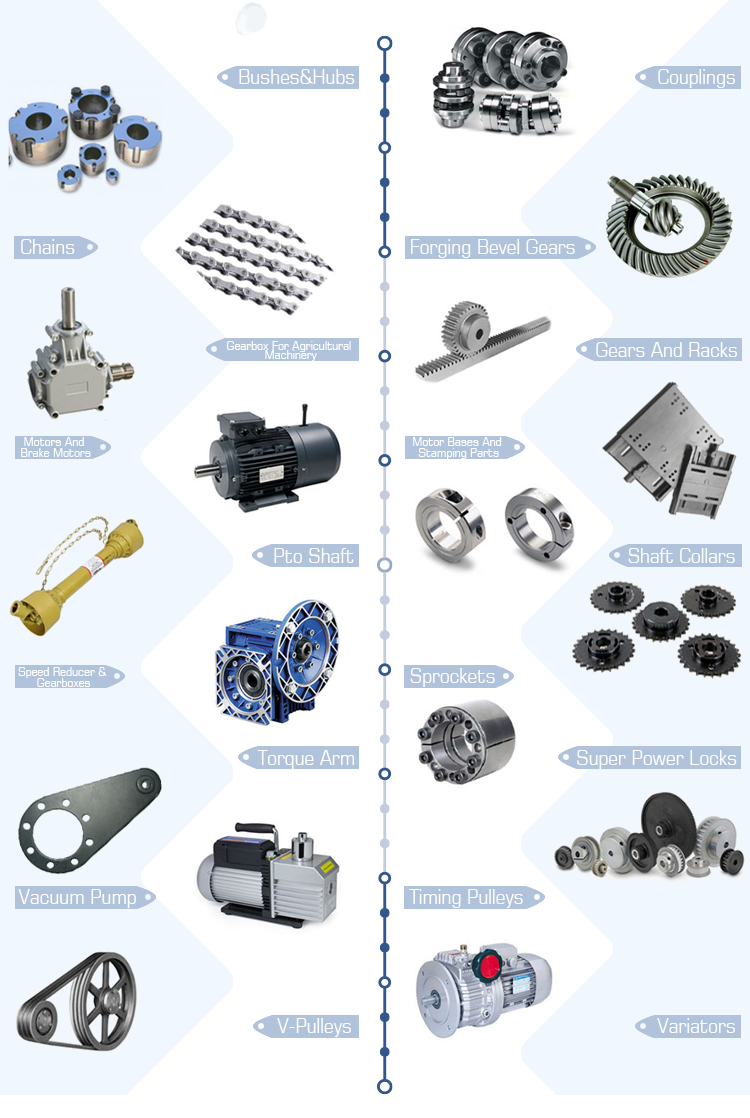
We can supply a total-assortment of electricity transmission goods like chains, sprockets and plate wheels, pulleys, gearboxes, motors, couplings, gears and racks. We have exported our products to Korea, Turkey, Bulgaria, Romania, Russia, Italy, Norway, the Usa, Canada, etc. Each and every procedure, each and every part, every single operate in EPG is demanded to be carried out a single stage pursuing an additional, carefully and cautiously, from material assortment, reformation to manufacturing accessories, from elements heat remedy to automated assembly, from quality control to product inspection and testing and from get dealing to soon after sales support. single shaft Coulter Mixer EPTT for FerEPTTzer Powder
Questions for Consumer:
You should response under inquiries and send out answers to electronic mail, and then we will send you supply as soon as attainable.
| one, What supplies do you combine? (Names of raw resources?) two, What is the EPTT fineness (or particle size)? (mesh, mm) three, What is the bulk density (or certain gravity) of mixed supplies? (kg/liter, kg/m3) 4, How several kgs or liters to be blended for each batch? 5, What is the distance from base discharge outlet to ground? (cm, mm, m) 6, What development components do you demand? (Remember to select underneath choice) A, all construction materials gentle steel B, make contact with areas stainless metal, non-get in touch with areas gentle steel C, all building resources stainless metal |
one Operating theory:
CMPS collection Plough Shear Coulter Mixer is comprised of horizontal cylinder-shaped trough, single shafts with plough shear agitators, high velocity choppers, top go over with opening(s), assist frame and EPTT unit. The plough shear agitators rotate to EPT resources transfer radilly substantial velocity choppers scatter the components so materials are mixed properly by rotation of plough shear agitators and large velocity choppers.
2 Efficiency amp attributes:
two.01 EPT: stainless steel 304 / 316L or delicate metal Q235
two.02 Area treatment: paint (moderate steel), polish/sandblasting (stainless steel)
two.03 Plough agitators amp choppers: portions count on mixer measurement
2.04 Mixer tank: horizontal, cylindrical tank
two.05 Shaft: horizontal, hollow, integral one shaft
two.06 MiXiHu (West EPT) Dis.ng time: 5-30minutes
two.07 Operating product: batch miXiHu (West EPT) Dis.ng
two.08 Velocity EPTT: cycloid EPTT
two.09 Rotation velocity: mounted speed
two.ten Primary shaft seal: (Teflon) stuffing seal or air purge seal
two.11 Openings: feeding inlet, manhole, and inspection amp relationship port
2.twelve Discharge valve: pneumatic or manual flap discharge valve
two.13 Working situation: NPT (regular pressure and temperature)
2.fourteen Not large obligation: mixer can not be started with loading components
2.fifteen EPTT supply: 220V 50HZ one phase/ 380V 50HZ 3 stage
2.sixteen Non ex-proof electronics (motor, electronic factors, control cabinet)
three Optional characteristics:
The adhering to optional attributes are obtainable: dress in-resistant and anti-corrosion supplies, floor therapy constant miXiHu (West EPT) Dis.ng EPT box EPTT changeable velocity mechanical seal EPT openings and discharge valves temperature management pressure need hefty-obligation configuration motors, digital components, electronic handle panel are EPT to various EPTT and ex-evidence requirements ligEPTT EPT sampling device liquid spraying unit scrappers and many others.
four EPTnical requirements:
| Mixer model |
Functioning volume (L) |
Rotation velocity (rpm) |
EPT EPTT (kw) |
Total dimension (mm) |
EPTT bodyweight (kg) |
| CMPS-fifty | twenty-30 | eighty | 1.1 | 1400 times580 times650 | three hundred |
| CMPS-a hundred | 40-60 | 80 | two.two | 1600 times680 times800 | four hundred |
| CMPS -three hundred | a hundred and twenty-180 | 80 | four | 2000 times800 times1100 | 700 |
| CMPS -five hundred | two hundred-three hundred | 80 | 5.five | 2600 times1000 times1200 | 950 |
| CMPS -one thousand | four hundred-600 | 80 | eleven | 3000 times1250 times1300 | 1650 |
| CMPS -2000 | 800-1200 | 60 | eighteen.fifty five | 3600 times1500 times1700 | 2200 |
| CMPS -3000 | 1200-1800 | 60 | 22 | 4000 times1600 times1800 | 3200 |
| CMPS -4000 | 1600-2400 | 60 | 30 | 4500 times1600 times2000 | 4500 |
| CMPS -5000 | 2000-3000 | 40 | 37 | 4700 times1800 times2100 | 5500 |
| CMPS -6000 | 2400-3600 | 40 | 37 | 5000 times2000 times2300 | 6500 |
| CMPS -8000 | 3200-4800 | 20 | 45 | 5300 times2300 times2500 | 7500 |
| CMPS -ten thousand | 4000-6000 | twenty | 55 | 5900 times2300 times2500 | 9500 |
| CMPS -12000 | 4800-6000 | fifteen | fifty five | 6200 times2400 times2600 | 11000 |
| CMPS -15000 | 6000-9000 | 15 | seventy five | 6400 times2600 times2850 | 12000 |
| CMPS -20000 | 8000-12000 | 12 | 75 | 6800 times2700 times3100 | 13000 |
five Mixers Album:
six Application Industry:
seven Factory Album:


China manufacturer & factory supplier for double in Bacoor Philippines chain sprocket duplex triplex single roller chain plate wheel gear pulley sheave shaft collar motor base slide sprockets With high quality best price & service

EPG is a major supplier of large good quality, cost-efficient electricity transmission components. As our merchandise lines keep on to expand to fulfill our customer’s wants, our commitment to personalised customer services and on-time shipping and delivery continues to be next to none.We inspect every single piece of bearing by ourselves ahead of supply.
Overview
Fast Details
- Relevant Industries:
-
Manufacturing Plant, roller chain sprocket
- Area of Origin:Zhejiang, China
- Model Title:
-
OEM
- Design Quantity:
-
03/04/05B/06B/08B/10B/12B/16B/20B/24B/28B/32B
Provide Capability
- Provide Potential:
- one million Piece/Items per Month double chain sprocket
Packaging & Delivery
- Packaging Details
- Standard sea worthy package
- Port
- Shanghai or Ningbo
-
Direct Time
: -
Quantity(Bins) 1 – 99999 >99999 Est. Time(times) twelve To be negotiated
On the web Customization
Item Description


sprockets, sprocket for industrial utilization, industrial sprocket, sprocket wheel, pinion, chain wheel, black sprocket, iron sprocket, metal sprocket, c45 sprocket, cast iron sprocket, aluminium sprocket, aluminum sprocket, alumina sprocket, copper sprocket, ss sprocket, stainless steel sprocket, ss304 sprocket, particular sprocket, sprocket with keyway, normal sprocket, sprocket with spline, hardened sprocket, 06B sprocket, 08B sprocket, 10B sprocket, 12B sprocket, 16B sprocket, 20B sprocket, 24B sprocket, 28B sprocket, 32B sprocket, 36B sprocket, 40B sprocket, 48B sprocket, 25 sprocket, 35 sprocket, 40 sprocket, 50 sprocket, 60 sprocket, 80 sprocket, 100 sprocket, 120 sprocket, 140 sprocket, 160 sprocket, a hundred and eighty sprocket, 200 sprocket, 240 sprocket, double solitary sprocket, double chain sprocket, double roller chain sprocket, weld on sprocket
common or specific sprocket as for each your drawing or sample offered
1. Rang of item
03/04/05B/06B/08B/10B/12B/16B/20B/24B/28B/32B
twenty five/35/forty/forty one/fifty/60/eighty/one hundred/a hundred and twenty/one hundred forty/one hundred sixty/180/200/240
two. Max. processing diameter:ø=1450mm
The sequence of concluded-bore sprocket
1. Rang of merchandise
06B/08B/10B/12B/16B/20B/
35/forty/41//fifty/60/80/100/120/a hundred and forty/a hundred and sixty
two. Max. processing diameter:ø=1450mm
Taper bore sprocket of BTL sequence
one. Rang of product
06B/08B/10B/12B/16B/20B
35/40/forty one//50/60/80/one hundred/a hundred and twenty/a hundred and forty/a hundred and sixty
two. Max. processing diameter:ø=1450mm.
Max. coordinated taper bush:8065
Taper bore sprocket of QTL collection
1. Rang of product
35/40/forty one//50/60/80/100/one hundred twenty/140/one hundred sixty/200
2. Max. processing diameter:ø=1450mm.
Max. coordinated QD coverThis way of operating creates synergies among the distinct products if we insert a quite dynamic and specialist coverage, the consequence is a substantial profitability in strategic offers, that warrants the reward of our consumers.:N
STL taper bore sprocket
one. Rang of merchandise
35/40/forty one//50/sixty/eighty/one hundred/120/a hundred and forty/one hundred sixty/two hundred
two. Max. processing diameter:ø=1450mm.
Max. coordinated Browning protect:U2
Molten sprocket wheel
one. Rang of merchandise
06B/08B/10B/12B/16B/20B/24B(technological-bore & BTL taper bore)
We feel honoured to offer you created to purchase product.
2. Max. processing diameter:ø=1450mm. Max. coordinated taper
bush:5050
three. Max. fat of the casting 2000kg.
Coarse pitch conveyor sprocket
1. Rang of product
P50/EPG manufacturer rotocultivator ploughshares in T. line have been picked as the Nationwide Rotary Tillage Machinery Market “Excellent Model Merchandise” in 2007 by Rotocultivator Department of China Agricultural Machinery Industry Affiliation. P75/P100/P50.eight
BTL taper bore sprocket of common sequence
one. Rang of merchandise
06B/08B/10B/12B/16B/20B
35/forty/fifty/60/eighty/a hundred/a hundred and twenty/one hundred forty/160
Flat-prime conveyor sprockets
1. Rang of solution
P 1/2″
Idle gear
one. A PTO shaft transfers the energy from the tractor to the PTO powered attachment. This permits the tractor to electricity a selection of tractor implements including flail mowers, wood chippers, rotary tillers, excavators, and a lot more. Rang of solution
06B/08B/10B/12B/16B
35/40/41/fifty/60/eighty
Worm wheels &Worms
one. Rang of product( Module M1M3,Stress angle20°
two. Rang of solution( diametral pitch 4DP16PD,
Pressure angle14.5°
Cylindrical spur gears
one. Rang of solution( Module M1M6,Pressure angle20° Pierce
two. Rang of solution( diametral pitch 4DP16PD,Stress angle20°/14.5°. STL taper bore
Straight bevel gear
1. Rang of item( Module M1.5M5,Force angle20° Pierce
two. Rang of merchandise( diametral pitch 4DP16PD,Pressure angle20°/fourteen.5° STL taper bore
Major Merchandise
Company Details
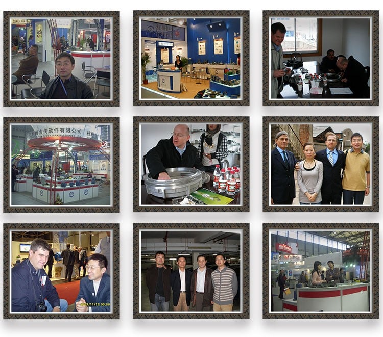
Exhibition
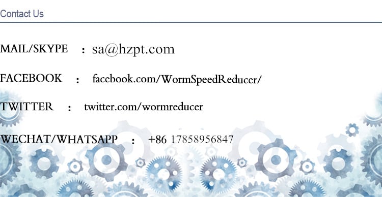
Speak to Us